I finished up the mechanism on the P-2 and reassembled it shortly after my last website update. I tested it with an MRC DC power pack and it seems to run fine now.
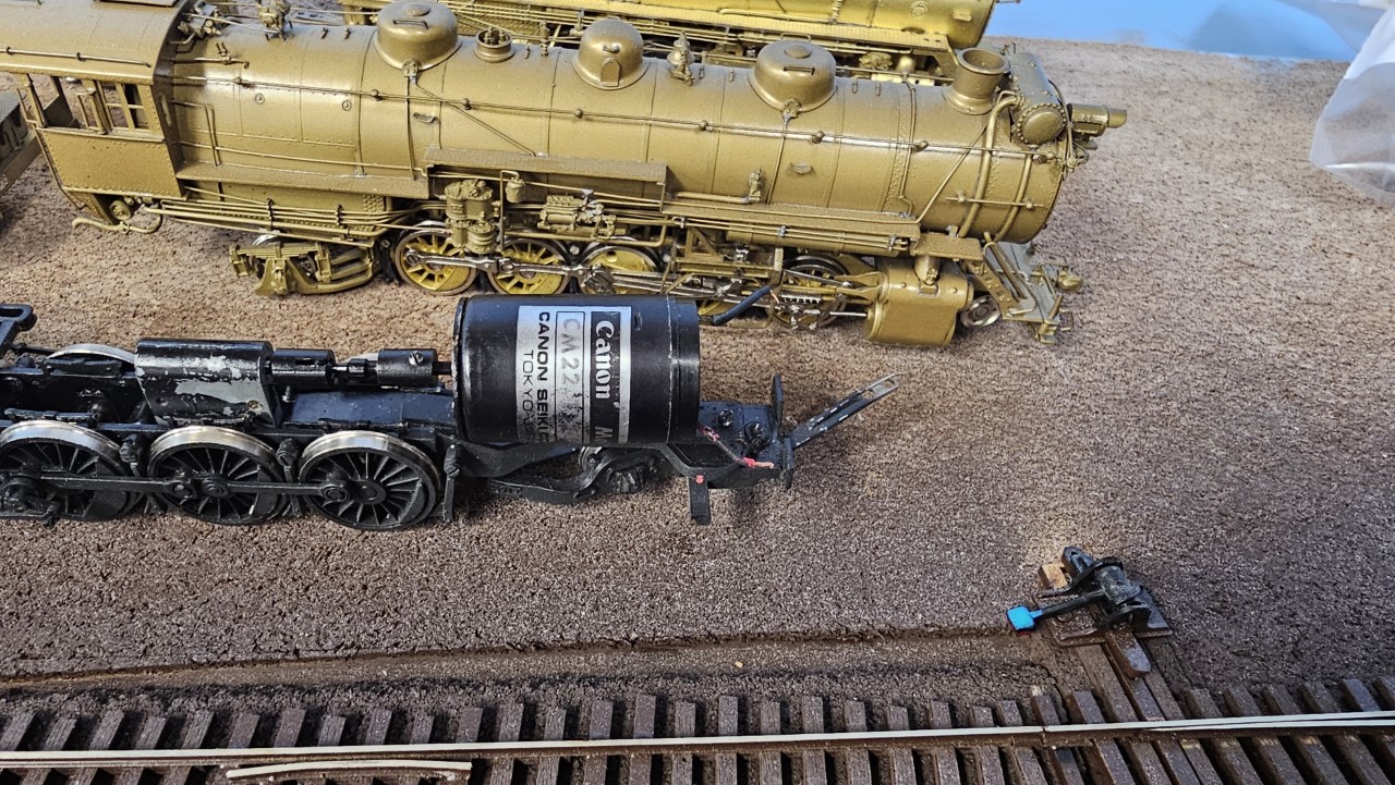
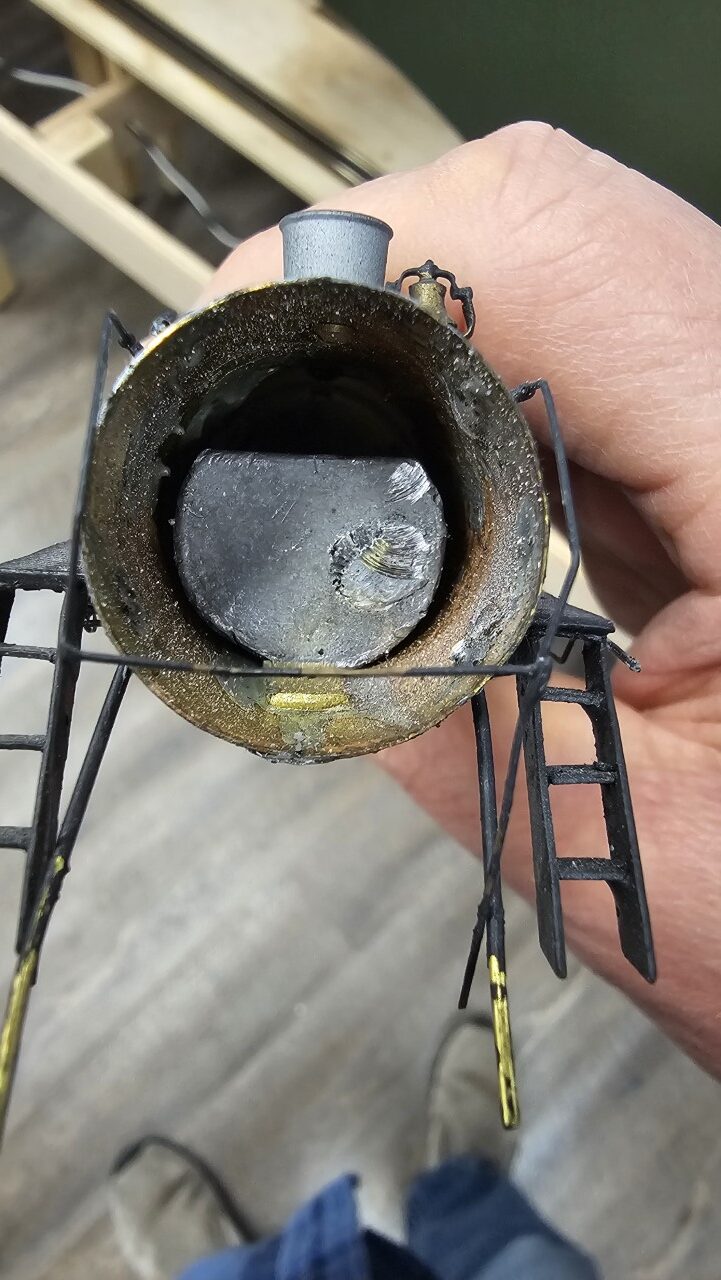
The only other thing I did to the P-2 was clean up the inside of the smokebox so the speaker would fit better, in late February. Beyond that I've done nothing since February. I might get back to the loco in April.
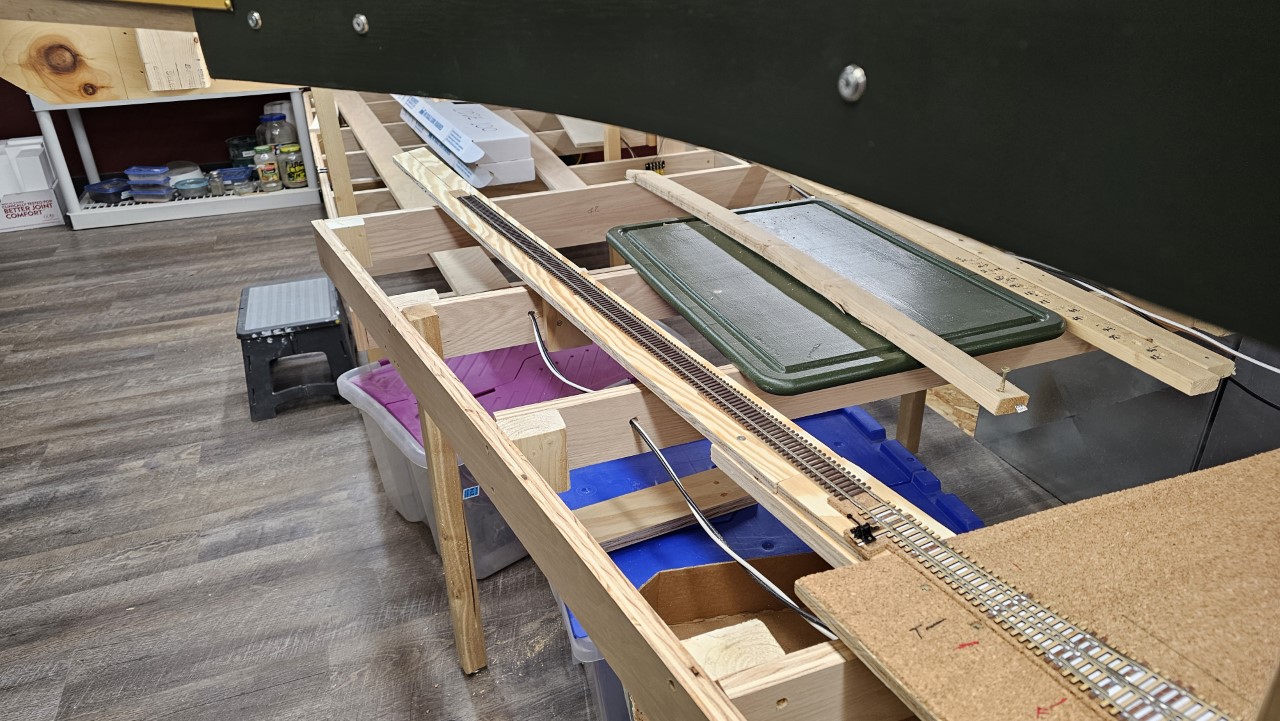
In the middle of February I added a temporary tail track to the marshalling yard at Cody so the yard could actually be used. When the last section of Cody is built and installed this will go away. While I was working in the area I finished wiring all the tracks in the area. Here's that tail track:
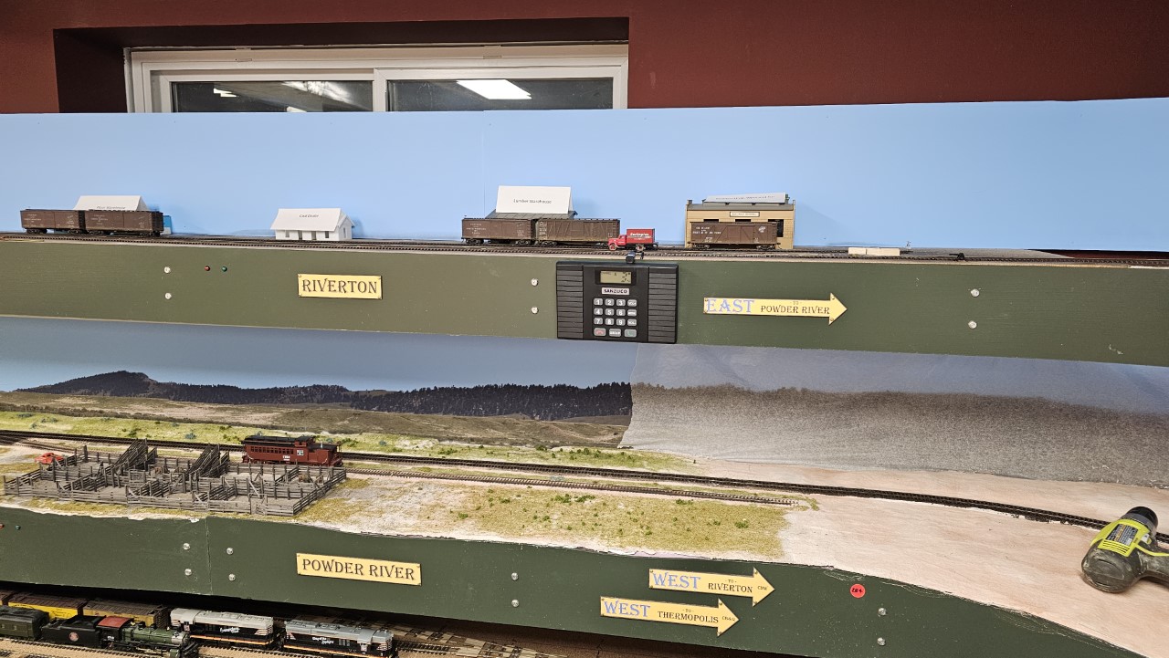
Then I did some things around the layout to enhance operation sessions. One big thing was to install five intercom stations around the layout. This is an interim step towards a dedicated phone system. Here's the intercom at Riverton:
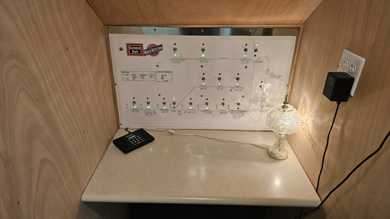
This is the dispatcher's desk with the new intercom there. There are a total of six stations - five on the layout and the one in the dispatcher's office.
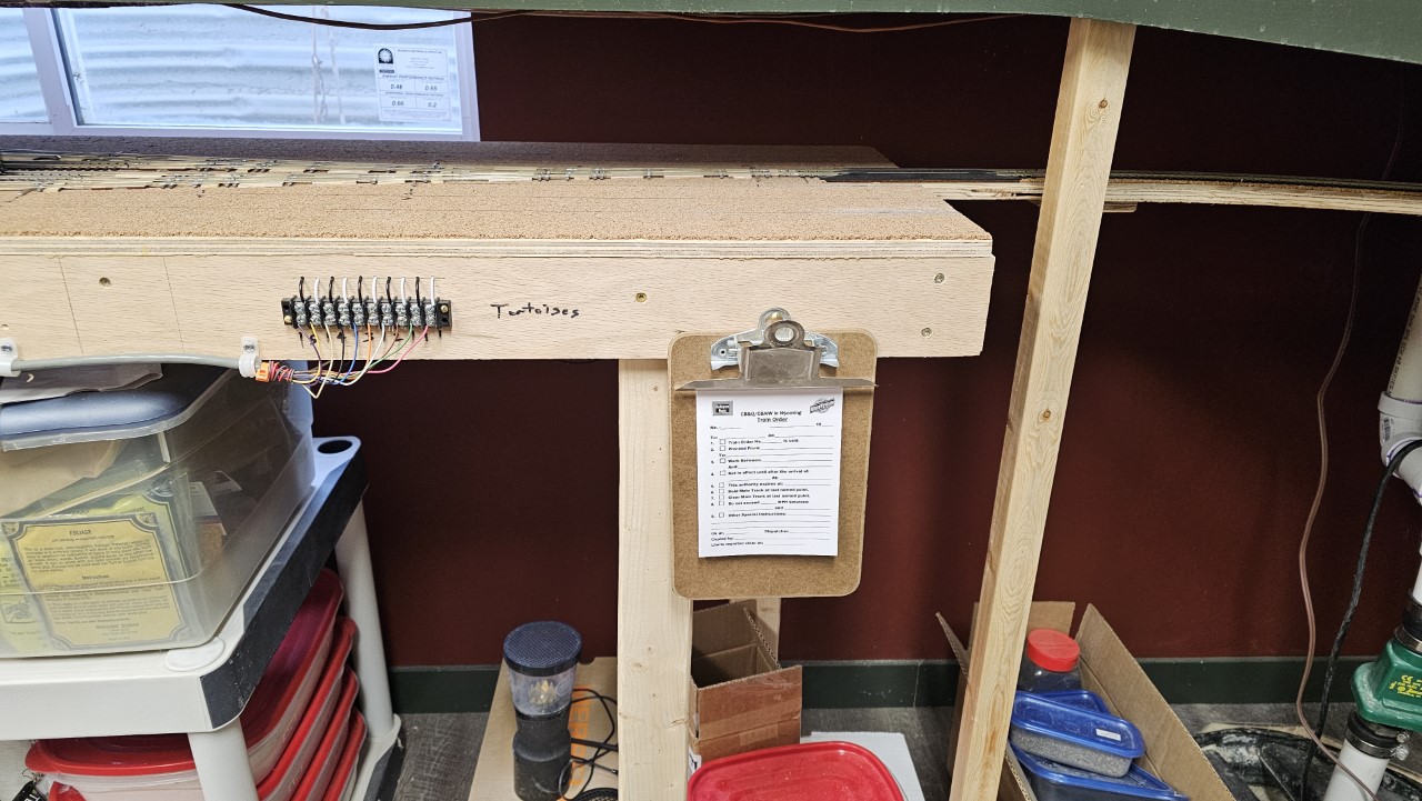
To go along with the intercoms I added small clipboards with blank train orders near the intercoms. Having the operators write their own train orders which the dispatcher dictates over the intercoms, it will eliminate the traffic jam near the dispatcher's desk and reduce the dispatcher's paperwork. This clipboard is attache4d to the edge of the staging yard right underneath Riverton and Powder River:
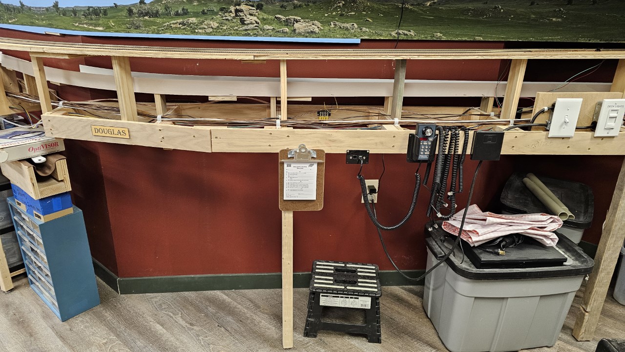
This is the clipboard at Douglas, right under the intercom installed on the fascia at Hudson:
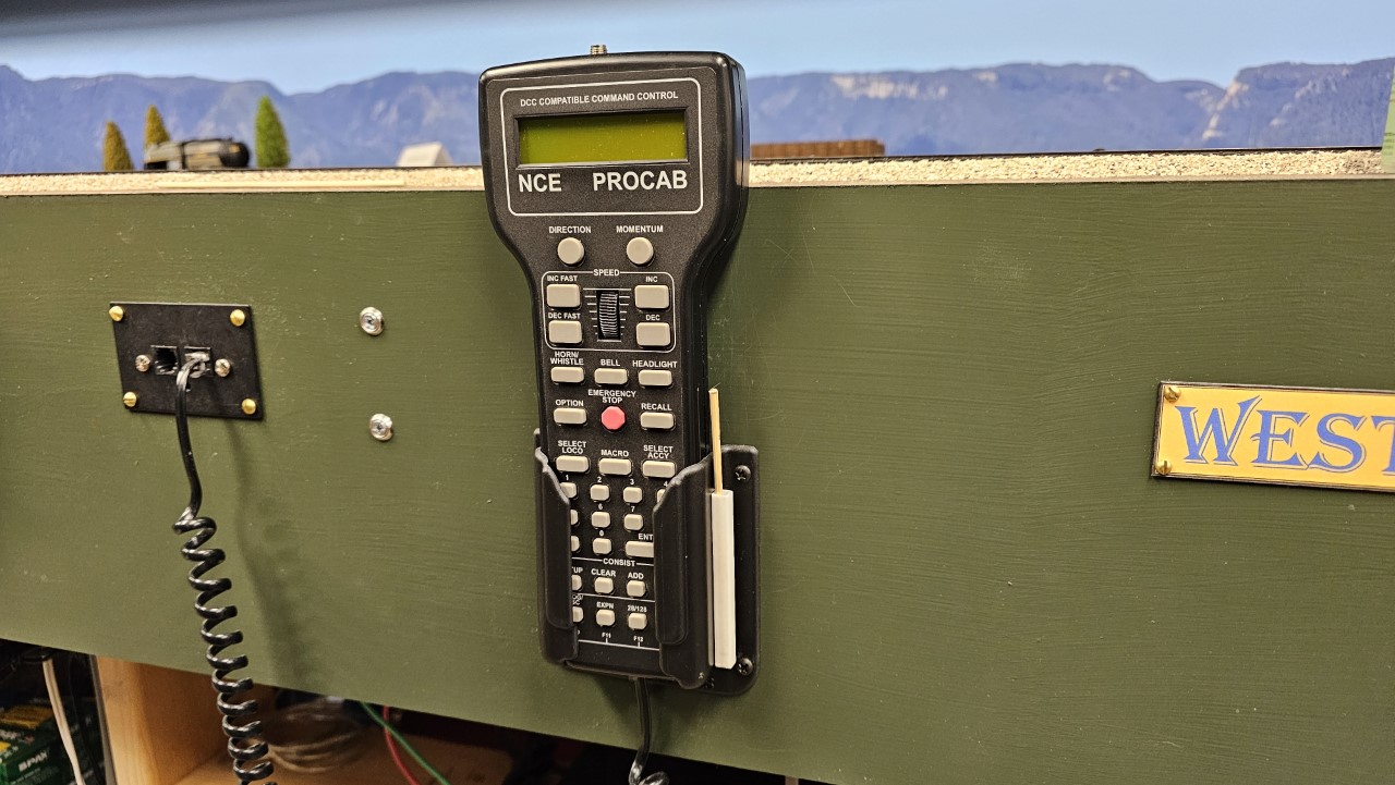
The next thing I did was add holders for uncoupling skewers on each throttle pocket, to stop people from just laying the tools on the layout (it was only partially successful).
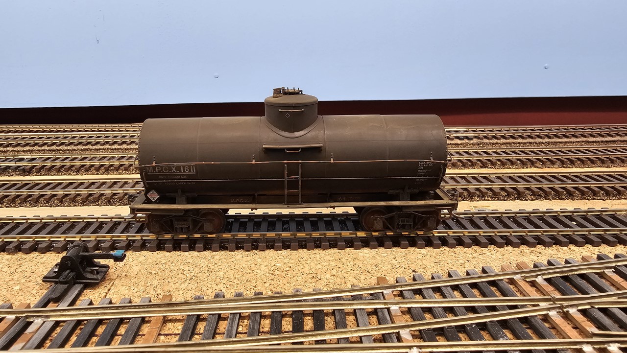
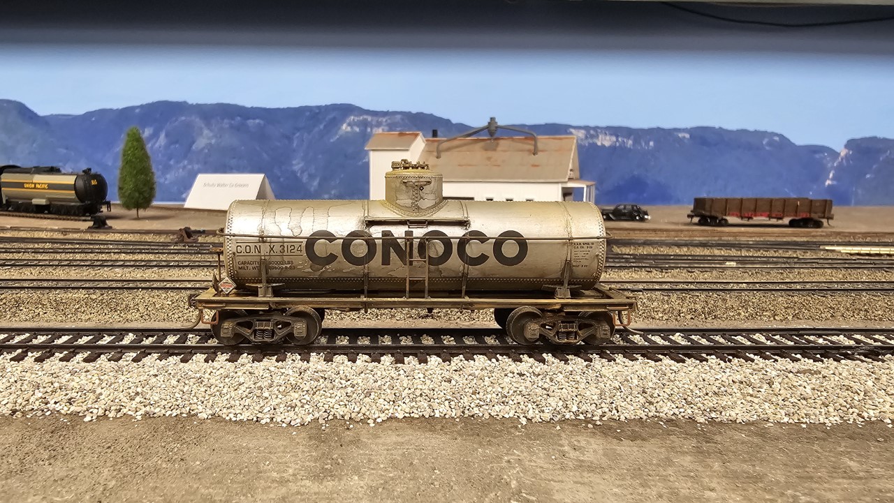
The last couple weeks of February, in between all the other stuff, I built five new tank cars, including one insulated tank car for use at Husky, which shipped mainly asphalt. Here's one of the new standard tank cars:
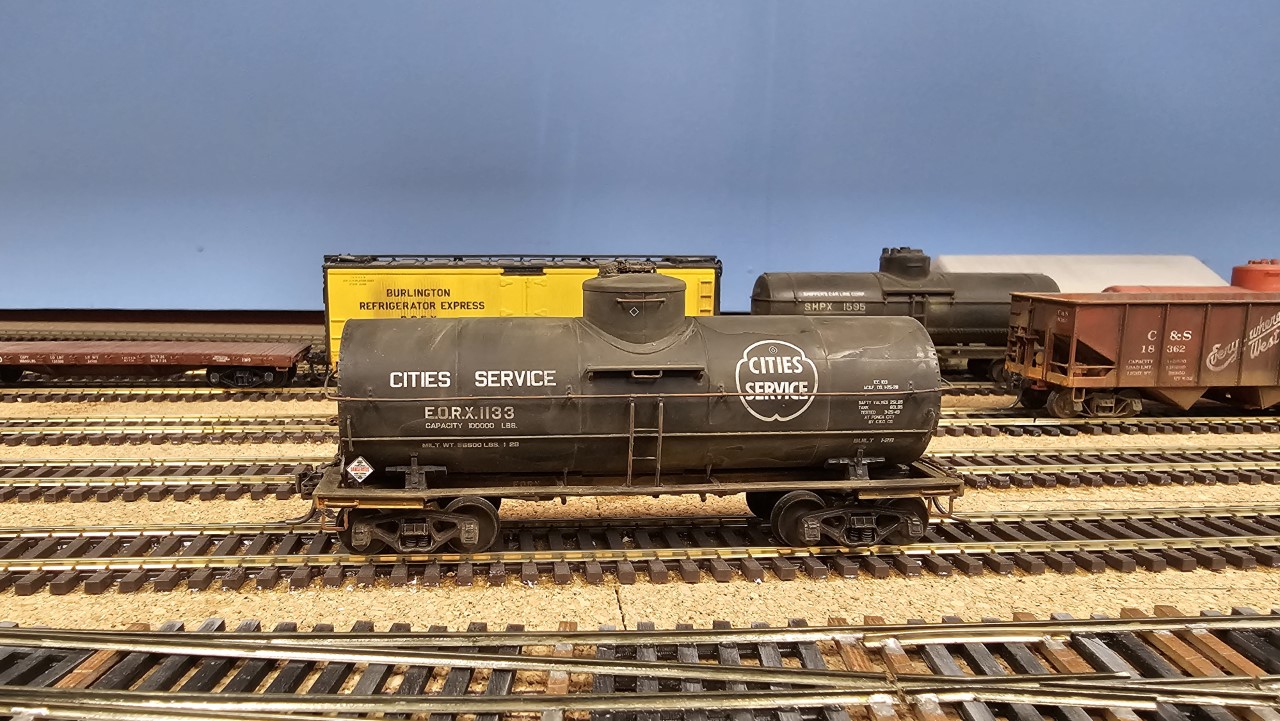
This is the insulated car. I only have two insulated cars but I need 25 or 30, so now I have something to look for at train shows for a while.
The two stub-end yard tracks at Greybull are near the edge of the benchwork, so I installed fencing to prevent an errant elbow from knocking cars to the floor.
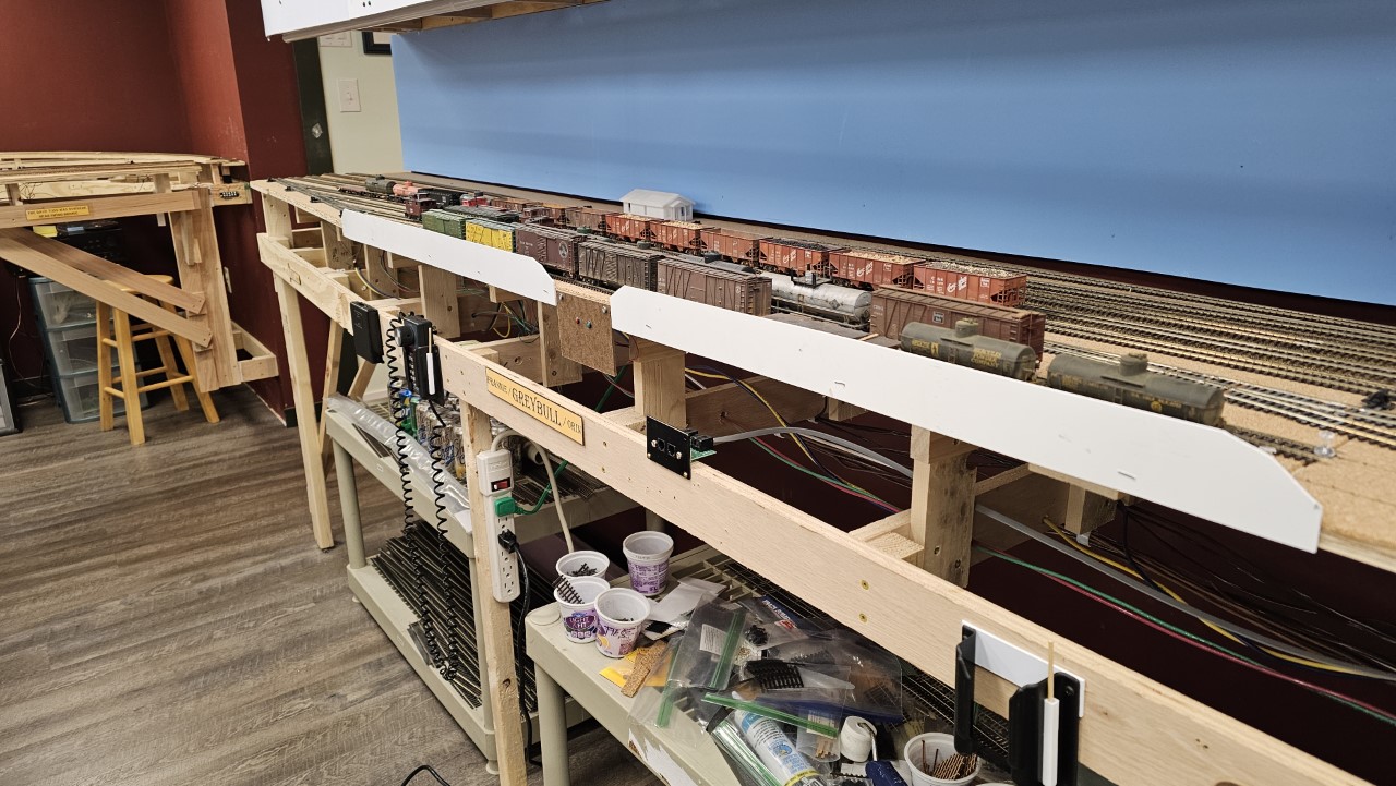
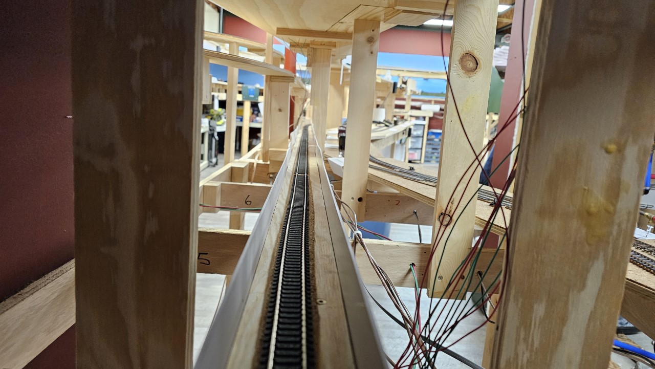
Since I was installing fencing anyway, I took a couple days after posting the March layout update to install fencing for most of the hidden track that didn't yet have any. I stopped when I ran out of styrene, with about six feet of track left to go. Here's the fencing installed on the line to east staging. Powell is to the right.
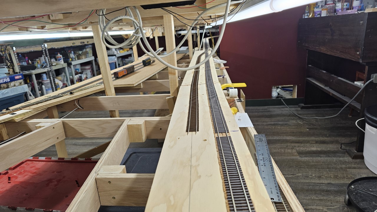
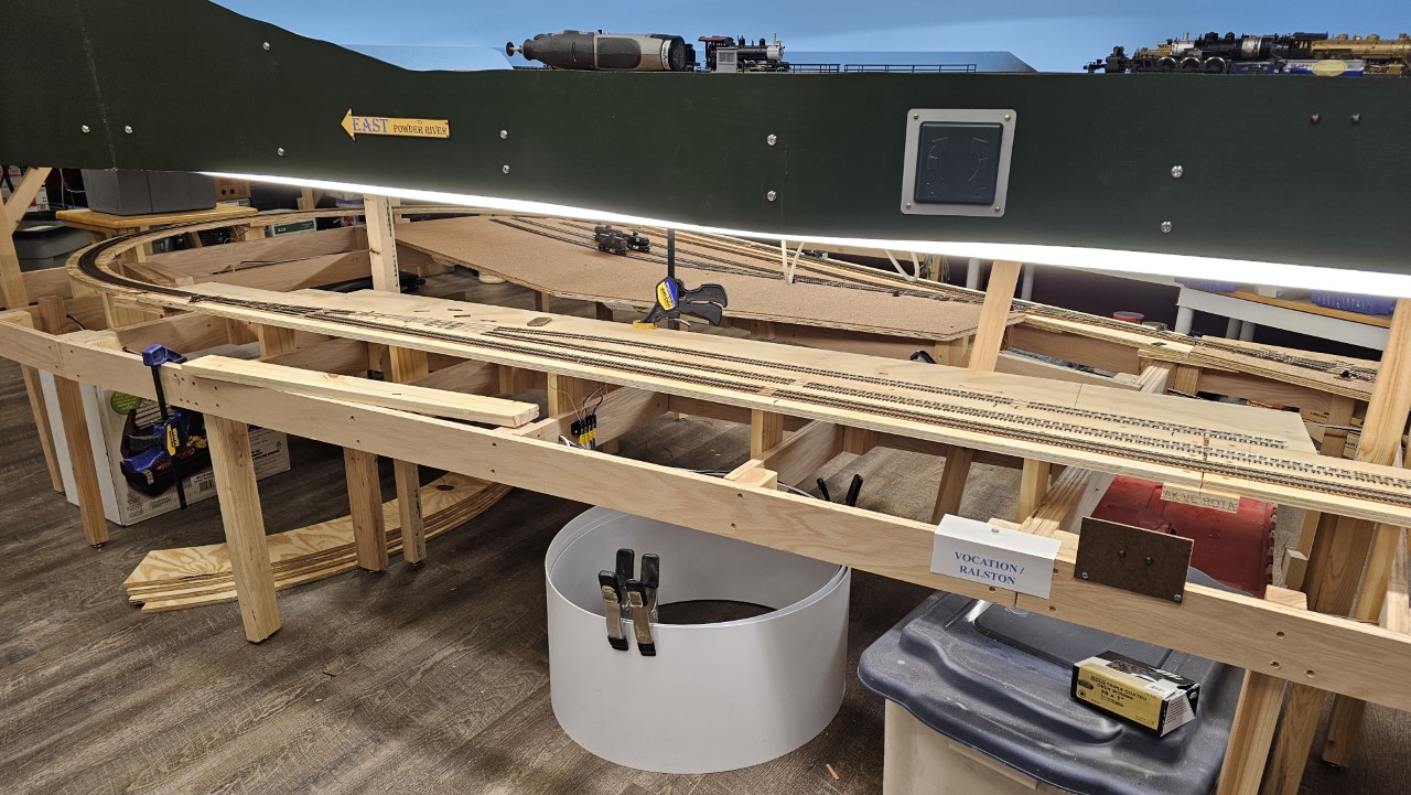
I spent several days the second week of March installing the Vocation tracks. The mainline was in, but the siding and industry spur weren't done yet. In this shot the siding is about halfway installed.
On March 11th I had the siding complete, including the turnout for the industry spur, but the ties and ground throw for that switch, plus the siding itself, weren't complete yet.
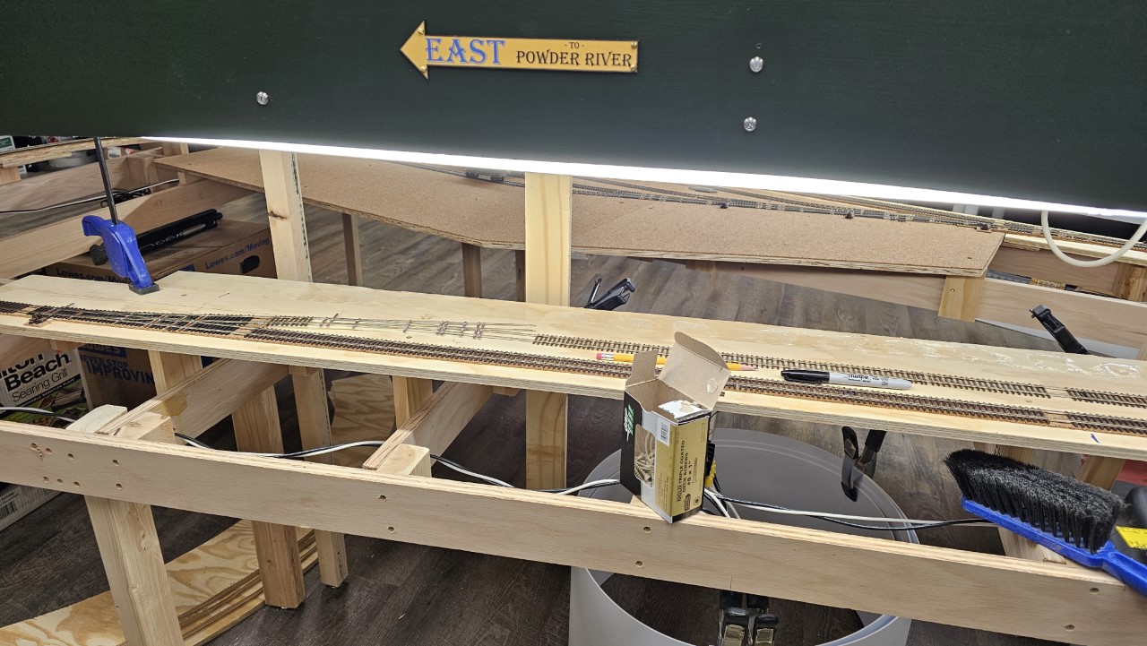
The next day the siding was in, but the turnout work was still to come. That was done on the 13th. Here's the trackage on the 12th:
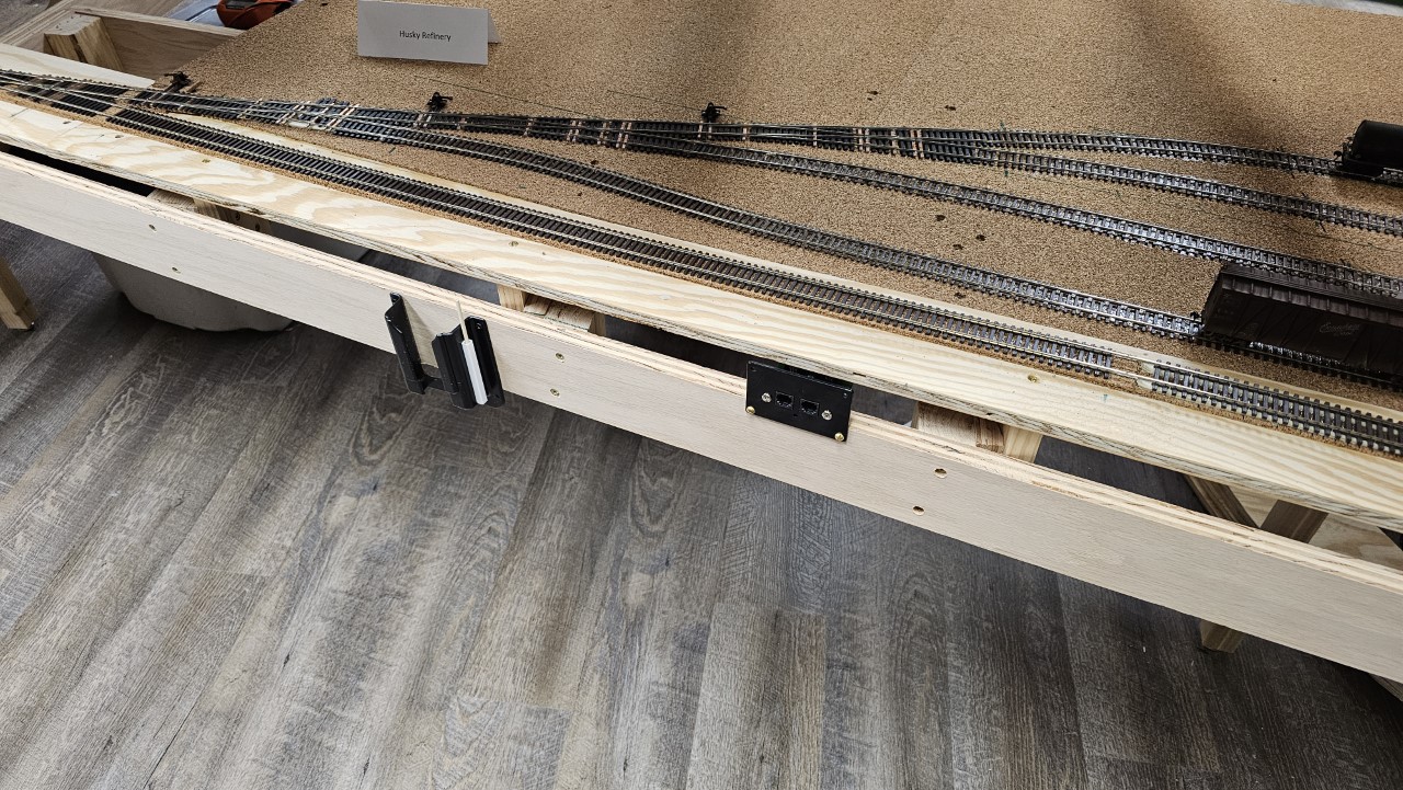
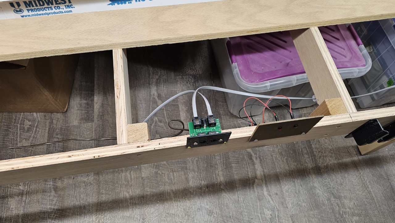
I didn't have any throttle ports installed at Cody yet, so whoever would run the Cody local would have to use a wireless throttle. Just before the March 24th session I installed ports at Cody, but I didn't get a chance to wire them up. Here's the port at Husky Refinery:
I spent the next twelve days getting the layout ready for the March 24th operating session - cleaning the room and the layout, generating train manifests and all that stuff.
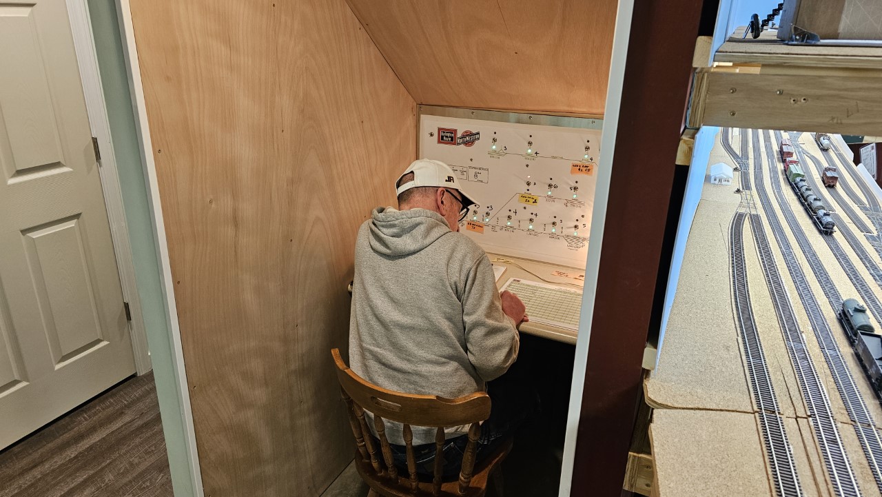
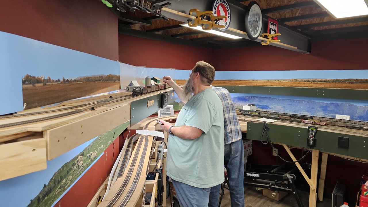
When the day arrived, Kevin agreed to be the dispatcher. Here he's hard at work in the middle of the session:
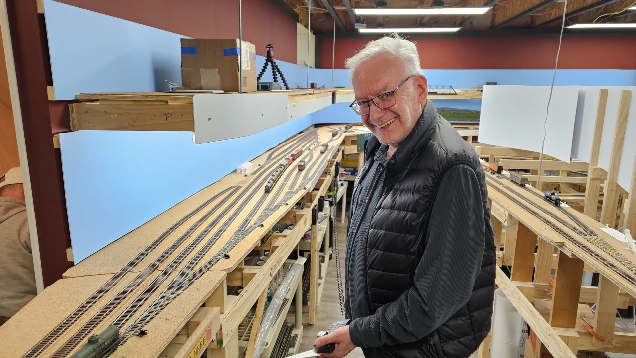
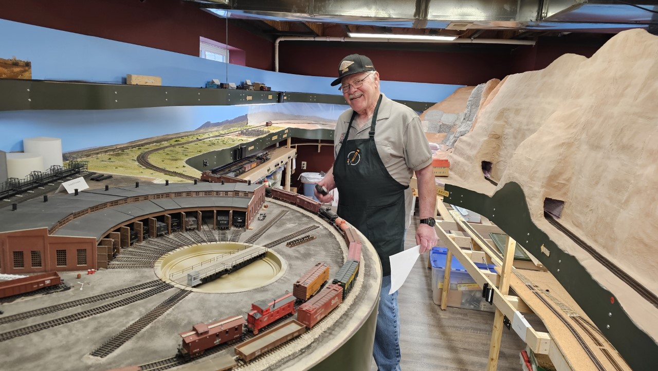
Rich seemed to be enjoying himself running Greybull yard:
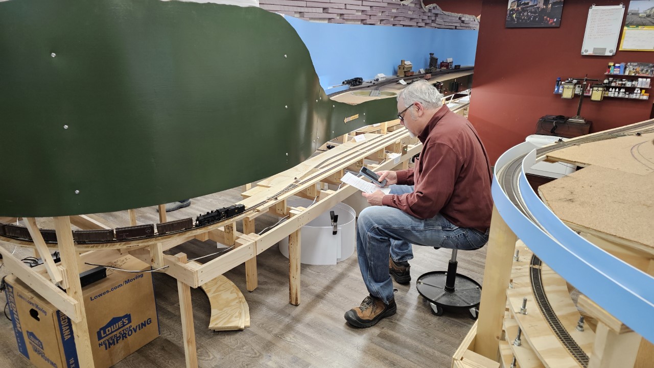
Alex ran the Cody local. Here he's switching Vocation on the way back to Greybull:
Mike ran the CNW local. Here he switching cars at Hudson.
Steve ran both of the through freights across the entire layout. Here he's bringing train 78, the eastbound one, into Casper.
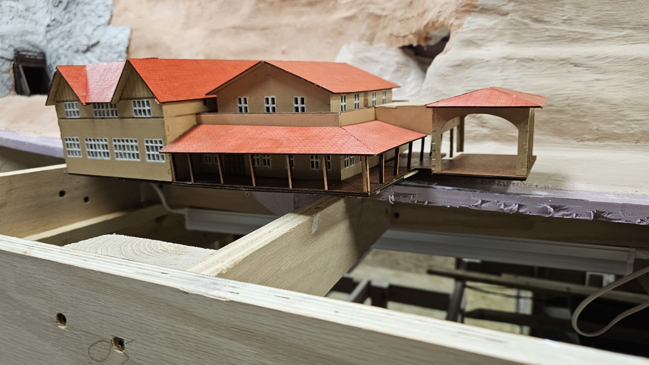
I planned to scratchbuild a model of the Burlington Inn in Cody at some point in the future, probably years from now. But a member of the Casper model railroad club recently got a laser cutter and offered to try to make a model for me. I sent him all the pictures of the Inn I could find, and he dropped this model off the day of the operating session. This is great - now I don't have to build one myself! This will be placed next to the tracks at the end of Cody when I get that last section built.
On April 4th I finally got those Cody throttle ports wired into the system.
While the freight car shortage on the layout is getting a bit better, every time I open a new section of the layout it gets worse again. Just the two sections of Cody that I recent brought into service will require 40 or 50 more cars at least, mostly for the Husky refinery. The remainder of Cody will require another ten or so cars, and Lander on the CNW is yet to be built. It will demand another fifteen to twenty cars to function properly.
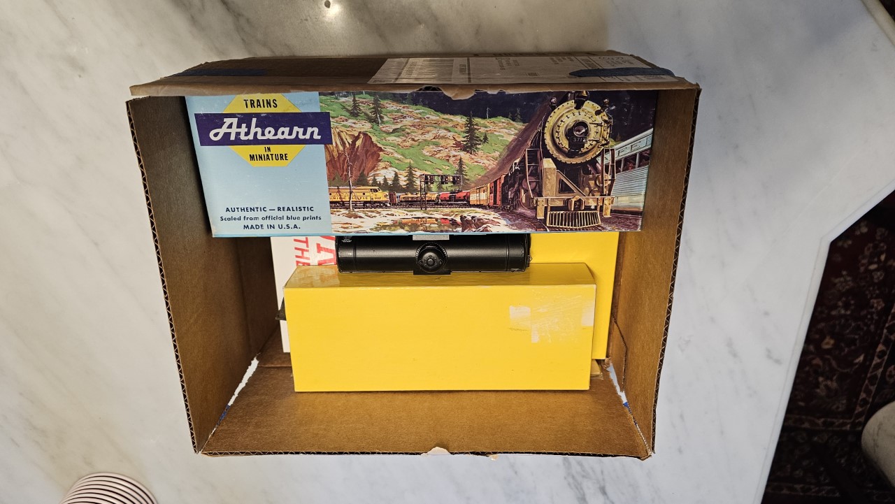
My good friend Dave decided to help out. He gave me this box of cars - eight boxcars and one tank car. All I need to do is add Kandee couples and wheels to most of them, then weather them and put them on the layout.
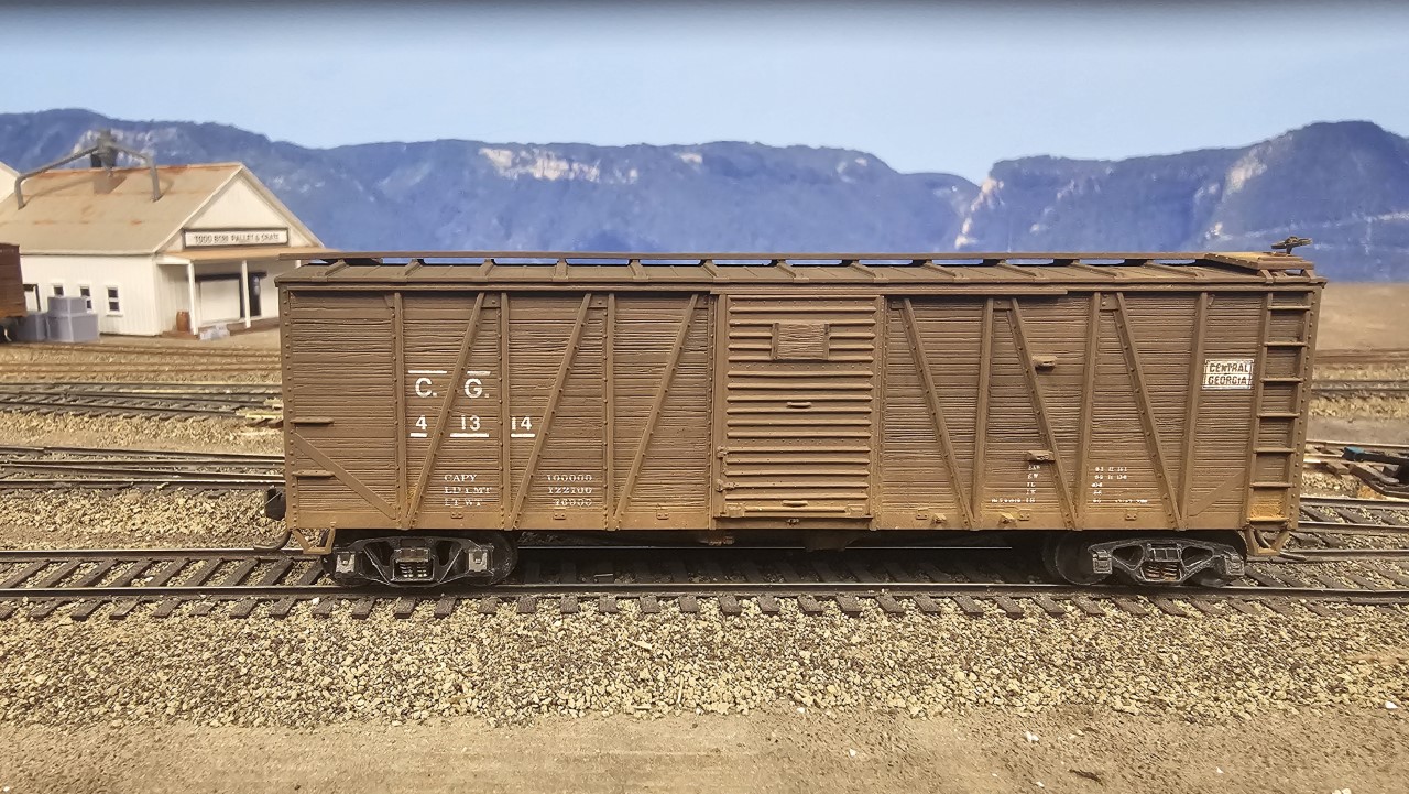
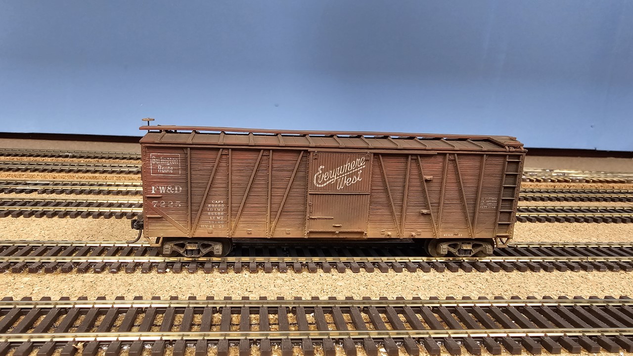
In the first three months of 2026 I've added 14 new cars to the layout, and more are in process. Three of the cars Dave me have already been added, including these two boxcars:
This is the second - and last - insulated tank car I have. I've reidentified a few of the standard tank cars I've got as asphalt cars for now, but that subtracts from the total available for the Standard Oil refinery in Casper and the Empire State Oil refinery in Thermopolis.