The Cove Road I Track Plan
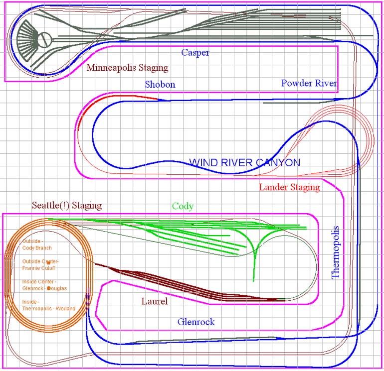
I designed the track plan for my Wyoming Division of the CB&Q using CadRail 7.11. It's a double deck plan, with a five-loop helix connecting the levels. Below are overall diagrams of the two levels. I've also included 12" gridlines in the overall diagrams to give a perspective of the size of this monstrosity. Those don't show up in some of the breakdown diagrams because they tend to obscure too much.
The lower level plan and overall scenic pictures are slightly out-of-date - Cody was moved to the left side of the helix, and Lander has been added to the plan in the spot where Cody is shown. Other track diagrams on the site have been updated with this new configuration. I never took the time to update the main plan diagrams - sorry.
Here's the LOWER LEVEL:
Here's the UPPER LEVEL:
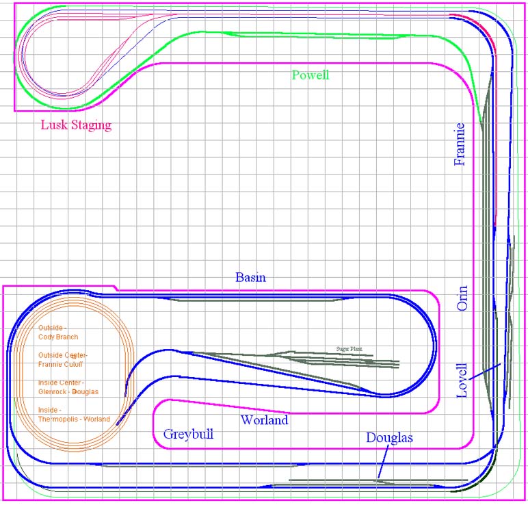
The big orange four-track oval near the bottom left of each diagram is, as you might guess, the four-track "helix" between levels. The magenta (purplish) lines are approximate benchwork outlines. The light grayish/blue gridlines are spaced at 12" intervals.
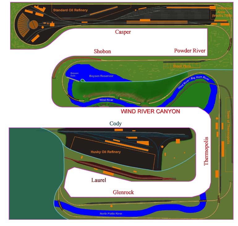
All that visible and hidden track looks like a bowl of spaghetti, so I put together a general scenicked representation of the railroad with only visible track showing, so I would have an idea of how things would actually look.
Here's the LOWER LEVEL:
And the UPPER:

The Wind River Canyon will sport scenery that reaches up near the ceiling, which is why there isn't a second level to that peninsula.
If you'd like to see something of the evolution of my modeling concept, plus some photos of previous layouts and their track plans (including the one that this plan grew directly from), take a look at the Old Track Plans page. If you'd like to see a much larger version of the scenic renderings for both levels, without the slight blurriness inherent in the reduced-size versions above, click here. Beware - this page will take a few minutes to load on a dial-up connection - there are two large pictures, each of which is over half a megabyte in size.
LINES
For ease of following train routes and interconnections between different parts of the layout, I've broken the plan down into the major different lines on the layout.
Clicking on the line name in the brief descriptions below, or on the button at the bottom of the page, will take you to that line's page. Looking over the System Schematic may also help tie everything together - it's a big layout! These lines are:
1. NP Mainline. This represents the NP transcontinental route through Laurel, Montana.
2. Frannie Cutoff. This is the CB&Q Mainline north of Frannie to Fromberg, MT, then the NP line on to Laurel, on which the Burlington had running rights. On the layout it's the entire connection from Laurel to Frannie, so I call it the "Frannie Cutoff." Like the NP mainline, its almost all hidden trackage, and is included for operational reasons. Many, perhaps most, trains coming from Laurel will pass right into the Wyoming Mainline without even stopping. The same is true of trains heading the opposite direction.
3. CB&Q Mainline. This is the "meat & potatoes" of the layout, and it represents everything from Frannie southeast to Orin Junction. This is most of the visible trackage on the layout, and where most of the action takes place.
4. Cody Branch. This is the stub-end branch from Frannie to Cody. In real life it runs along the northwest edge of the Big Horn Basin.
5. Lusk Staging. This is the continuation of the Wyoming Mainline past the end of the modeled portion at Orin Junction eastbound, into a four-track staging yard. I may try to increase that number of tracks - it sounds like too few to handle all the trains I'll need. Nearly all trains will pass through Orin Jct. without stopping. Orin Jct. actually was a dividing point where trains could head east to Nebraska or south to Cheyenne. The Chicago & Northwestern also met the CB&Q at this point. Orin is truncated on the layout - it's combined end-to-end with Frannie to provide for continuous running when I just want to watch trains roll, and has no further connection south - no room for more storage tracks!
6. CNW Lander Branch. The CNW takes off from the CB&Q at the junction at Shobon (just a single switch; not even a passing siding here) to duck into hidden trackage. It reappears at Lander.
Where appropriate and available, descriptions and photos of the real-life locations are provided, along with photos of the model (or of the blank floor if the model hasn't started).
ABOUT THE PLAN, AND COMMENTS ABOUT LAYOUT DESIGN SOFTWARE
As I said above, this plan was developed, in its entirety, using CadRail 7.11 & 8.01. Without it, defining this many levels of track and determining grades, while maintaining clearances wherever tracks are nested one over the other, would have made developing this plan much more arduous.
There are certainly flashier products on the market for track design, but from what I have seen only CadRail provided the serious design power needed for this layout. Years ago I tried using Abracadata's "Design Your Own Railroad," and quickly gave up on it because of its lack of sophisticated tools, and its "Gee, look what I can do" approach.
The interface design philosophy is very important, as the interface in may ways dictates the approach the designer must use. CadRail's no-nonsense, engineering design style interface works very well for me, because it matches the approach of the mainstream CAD packages, such as the one I use at work, CATIA. For what it's designed to do, CadRail performs its job admirably. It provides all the tools required to design a layout as complex as the one I've designed here.
What CadRail is not big on (intentionally, as I understand) is the "glitz." Pretty 3-D pictures are great, and they may help one visualize the finished layout to some degree, but in designing the layout, the substance, not the glitz, is what will buy your lunch, so to speak.